Guides
How to Build A Game Boy Macro With Our Faceplates
This guide will walk you through how to install our Game Boy Macro faceplate. This guide assumes you already have the appropriate soldering skills as well as all necessary parts / tools needed.
Disclaimer: This guide was written for informational purposes only. We assume no liability or responsibility for damaged equipment or for any injury you may incur attempting to replicate this guide. If you damage a 3D printed part during the install, please reach out and we can do a direct sale for a new part. However, no free replacements will be given for damage caused by your installation.

What you’ll need
- Our Game Boy Macro Faceplate
- Nintendo DS Lite
- Nintendo Switch speaker (x1)
- 330 ohm 0805 resistor
- Soldering iron
- Solder (Kester is great)
- Super Glue
- Kapton Tape
- Tri-Wing Y00 screw driver
- Phillips PH000 screw driver
- Tweezers
- Flush cutters (optional)
- Flux (optional)
- Desoldering Braid (optional)
- Masking Tape (optional)
- Light duty clamps (optional)
- Hot-air rework station (optional)
01. Assembling the Faceplate
In this section, you’ll need the following 3D printed parts: Game Boy Macro front faceplate, Game Boy Macro back faceplate, logo panel of your choice, and the LED Light Pipe. You will also need the Super Glue, optional masking tape, and clamps.


- Start by placing a paper towel under your work surface to protect it from any glue drops.
- Insert the small LED light pipe into the front faceplate.
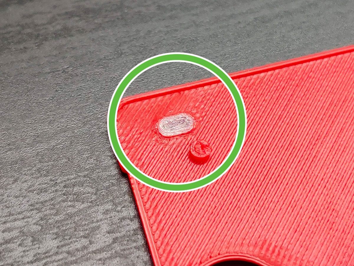
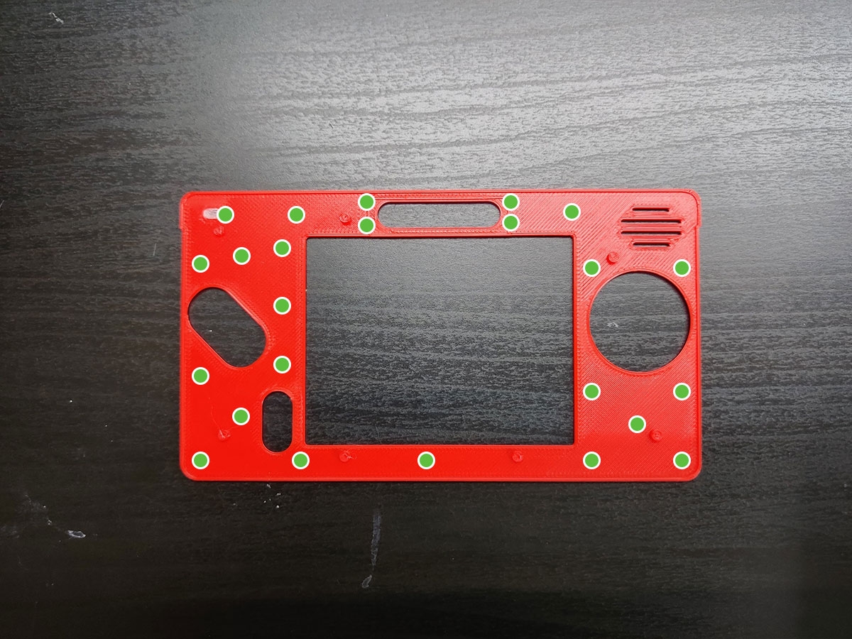
- Take your super glue and apply small dabs to the indicated locations.
- Be careful not to overdo it with the glue! If it leaks out it may dry white on the surface of your faceplate.
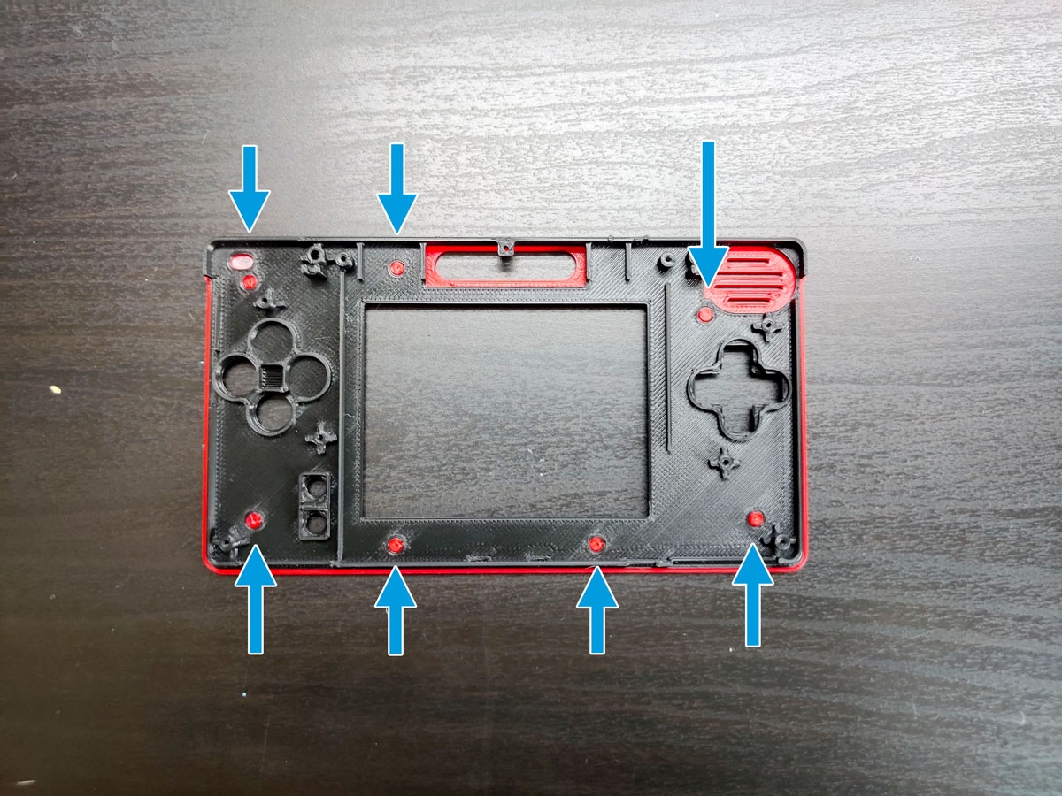
- Now take the back faceplate and visually line up its holes with the pegs on the front faceplate. Press down firmly until the all pegs are through the back faceplate.
- Now take the logo panel of your choice (“Macro” or “Game Boy”) and slide it into the logo hole of the back faceplate. Optionally, you can apply some glue on the back but just like before don’t use too much.
- Optional: use some masking tape to hold down the logo panel while the glue dries.
- Optional: use light duty clamps to hold the front and back faceplate together as the glue dries.
02. Removing Top Screen FFC/FPC Connector
In this section you will need a disassembled Nintendo DS Lite and a tool to remove the FFC/FPC connector (hot-air rework station, soldering iron, or flush cutters).


- Start by disassembling your Nintendo DS Lite. You can follow this guide on iFixIt.com
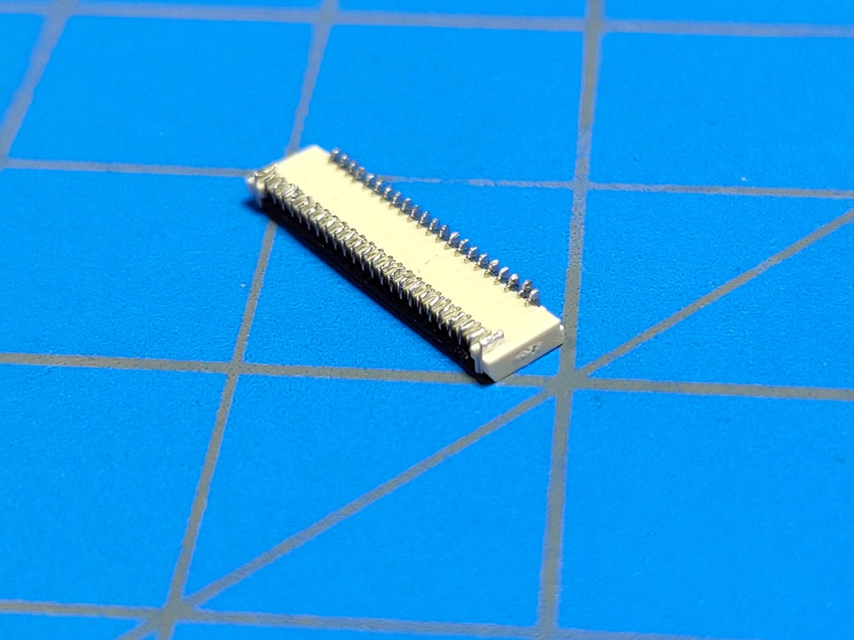
- If you do a quick fitment test of the faceplate and DS Lite motherboard, you’ll notice the the board won’t sit flat due to FFC/FPC connector hitting the Nintendo Switch speaker.
- You will need to desolder this connector using either a hot-air rework station (my preferred method), soldering iron and desolder braid, or by simply cutting the connector with flush cutters. The choice is yours.
- Once removed, it’s a good idea to clean up the area with an iron, flux, and desoldering braid.
- Apply a piece of Kapton Tape over the FFC/FPC pads just to be safe.
03. Installing the Speaker and Resistor
In this section, you will need the Nintendo DS Lite motherboard (with FFC/FPC connector removed), 330 ohm 0805 resistor, and Nintendo Switch Speaker, tweezers, solder, and soldering iron.

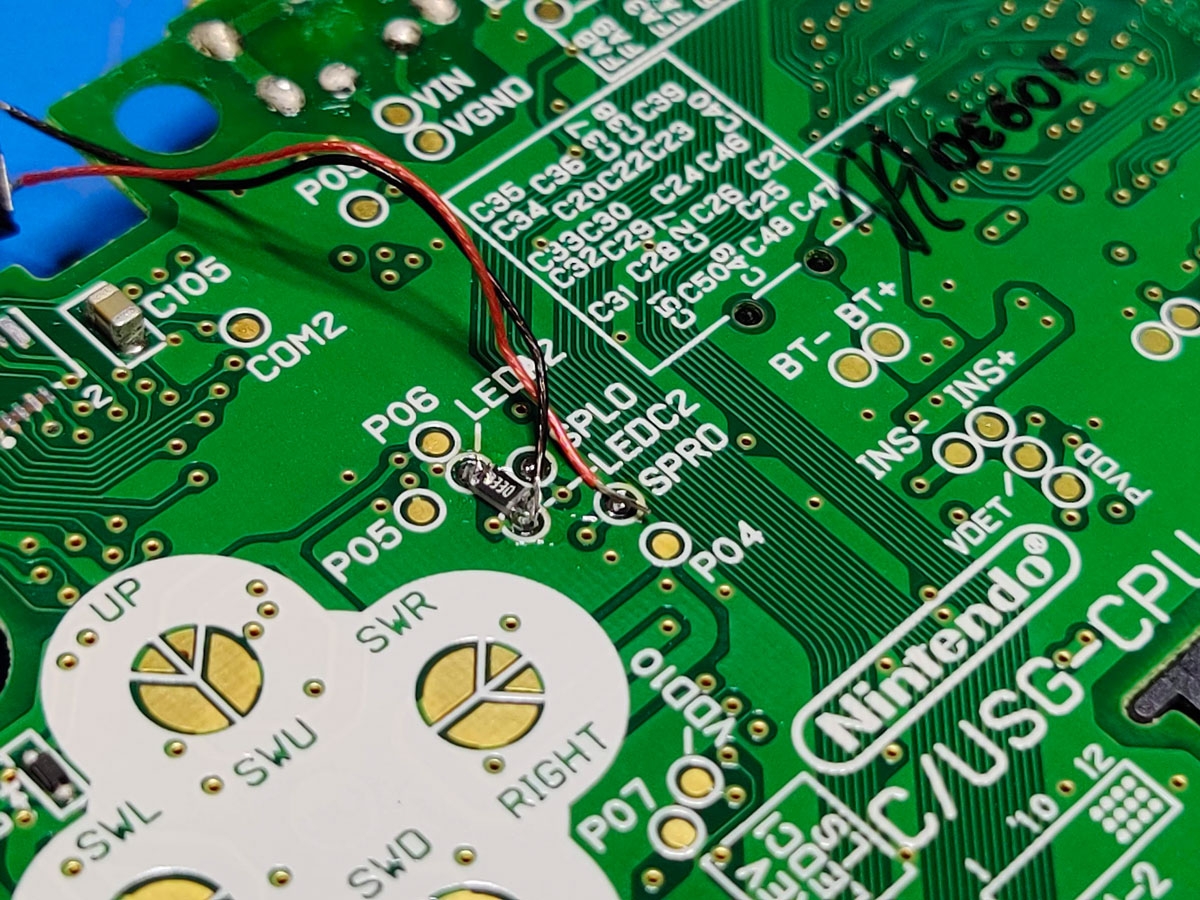

- You’re going to solder in a somewhat tiny resistor to test pads LEDA2 and LEDC2 on the motherboard. There’s a few ways to do this but I like to apply solder to one of the pads first, solder the one side of the resistor to that pad then finally apply solder to the other pad/side of the resistor.
- Apply a small amount of solder to test pad LEDA2. Using tweezers, hold the 330 ohm resistor between test pads LEDA2 and LEDC2 and solder down the one side to LEDA2. Now apply solder to the LEDC2 / other side of the resistor.
- Now apply a small amount of solder to SPRO. Take the positive side of the Nintendo Switch speaker (usually red or not black) and solder it to SPRO.
- For the speaker’s ground wire, you have plenty of options. I chose to use the LEDC2 side of the resistor since due to it’s proximity to SPRO but you can also use VGND or BT-. If you have a multimeter you can prob around for ground pretty easily.
- Once finished you can test everything is working by plugging in the screen, inserting a GBA cart, and holding the battery in place. Just be careful with the battery’s polarity.
- Before reassembly, make sure the screen’s digitizer and front glass are removed. The screen needs to be bare.
- If everything worked, you can now reassemble your new Game Boy Macro!