Guides
How to use a GDEMU to Replace Your Dreamcast’s Broken GD-ROM
I recently picked up a broken Sega Dreamcast on the cheap. I decided to modernize a few components to get it back to good working order. In my search for parts, I came across a something called a “GDEMU”, which is an Optical Drive Emulator (ODE) that replaces the entire GD-ROM unit in the Dreamcast. Being that my newly purchased Dreamcast’s GD-ROM was dead, this seemed like a perfect experiment. The only problem is, I couldn’t find one for sale. Well, that’s not entirely true. I couldn’t find a legitimate one for sale from the original creator, Neuroacid. This bummed me out but I did find a clone on eBay, which has a reputation for being just as good. I would loved to have been able to support the original creator but preorders have been closed for some time. Either way, you should head over to his site and read up on all the amazing work he’s done with ODEs.
What is a GDEMU and What can it do?
As I mention, the GDEMU is an Optical Drive Emulator, which replaces the Dreamcast’s GD-ROM with a custom board. The GDEMU has an SD slot, which holds all the game files. The GDEMU tricks the console into thinking its loading up original content directly from an optical drive when really its loading disc images from the SD card. It’s brilliant especially if your Dreamcast has a broken GD-ROM.
Installation Guide
Installation of the GDEMU is very simple and requires no soldering or cutting up of your Dreamcast. That said, there are other modifications you might want to do while you’re console’s apart, specifically removing the 12v rail on the power supply (PSU) but more on that later.
What You’ll Need
- Philips head screw driver
- 3D Printed Parts (optional)
- Prepared SD Card (not covered in this guide)
Disassembling the Dreamcast
- Flip the Dreamcast over and remove the modem to expose the screw under it.
- Now remove the four screws in the base:

- Gently flip the Dreamcast back over onto it’s base and lift the lid off the base. It should slide right off with a little force.
- Remove the 3 screws holding the GD-ROM in place, one is hiding behind the left side. Put these screws aside because we’ll need them in the next steps.

- Give the GD-ROM a firm upwards tug to release it from its motherboard connector.

- Here’s where the optional 3D printed parts come in handy. You don’t need to use these parts but they help retain proper airflow from the PSU. Alternately, you could use the stand off posts that come with the GDEMU. For the sake of this guide, I’ll cover using the 3D printed pieces.

- Drop the base 3D printed bracket into the Dreamcast and align the back screw hole to the GD-ROM’s screw hole.
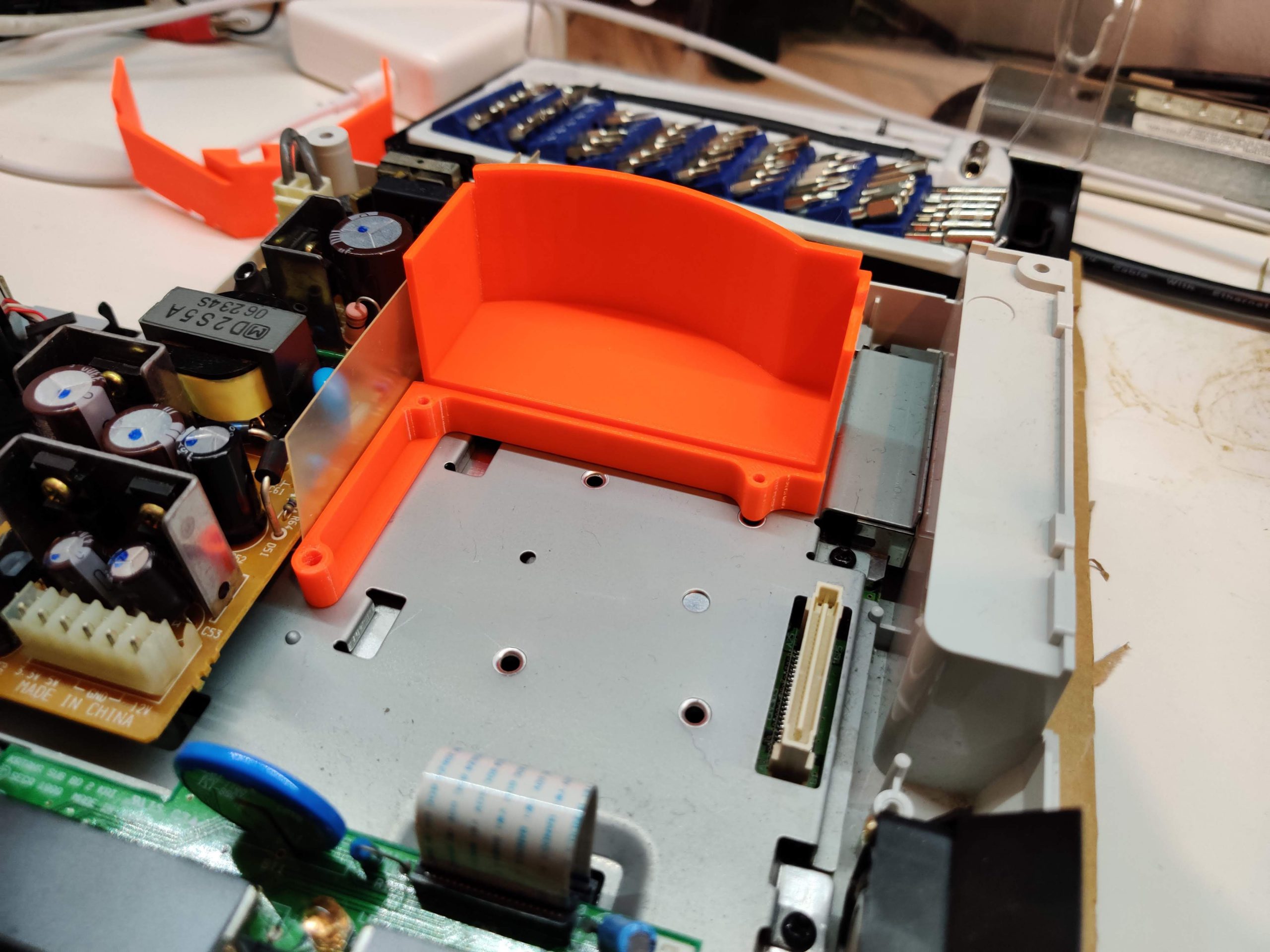
- Use one of the GD-ROM’s screws to hold it in place.

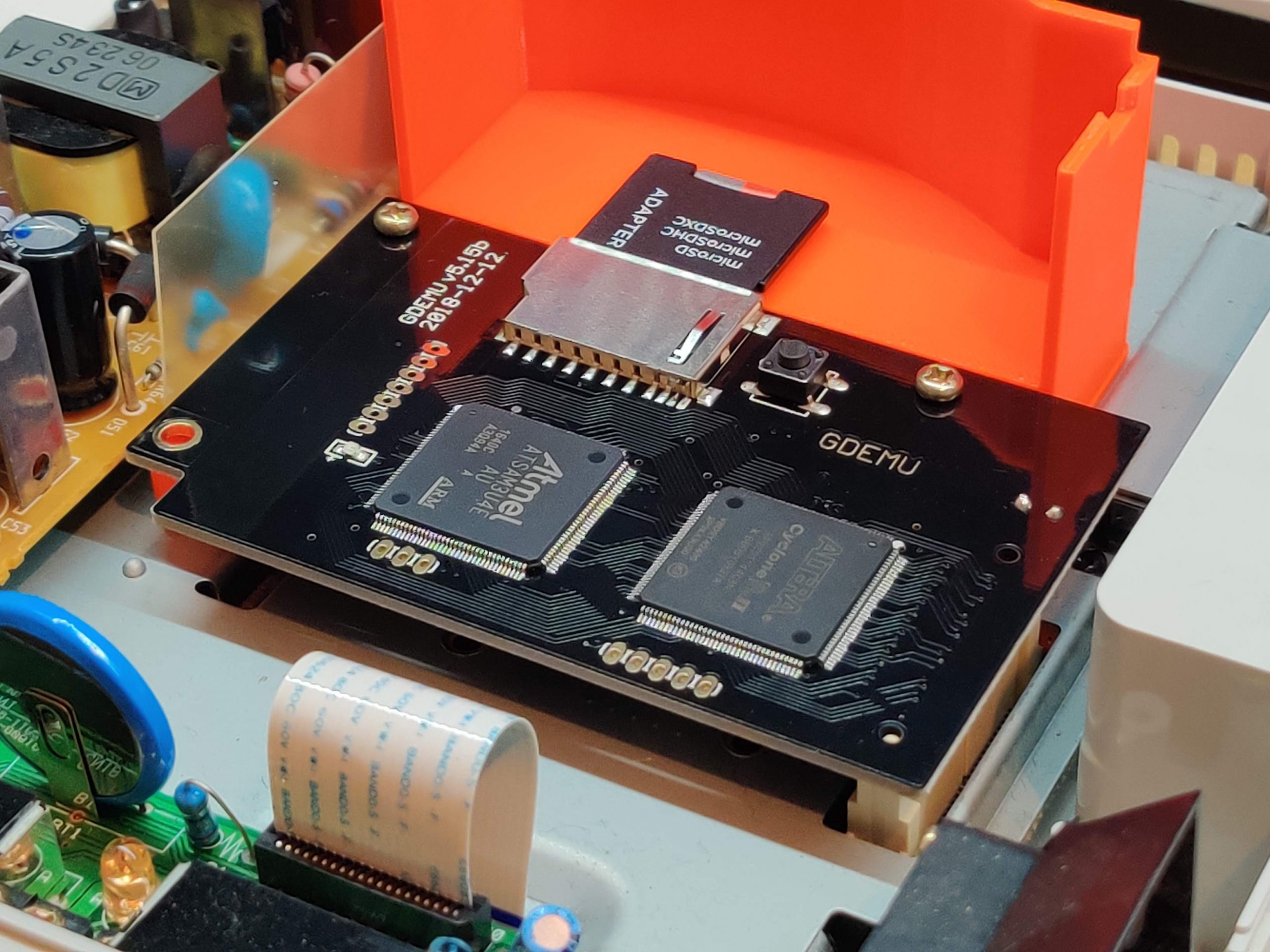
- Now, drop the GDEMU onto the bracket and align it to the screw holes.
- Using the remaining GD-ROM screws, tighten the GDEMU down to the bracket. If your GDEMU came with a screw, add it to the last screw hole and tighten it down. Note: clone GDEMUs may not come with the last screw – mine did not.
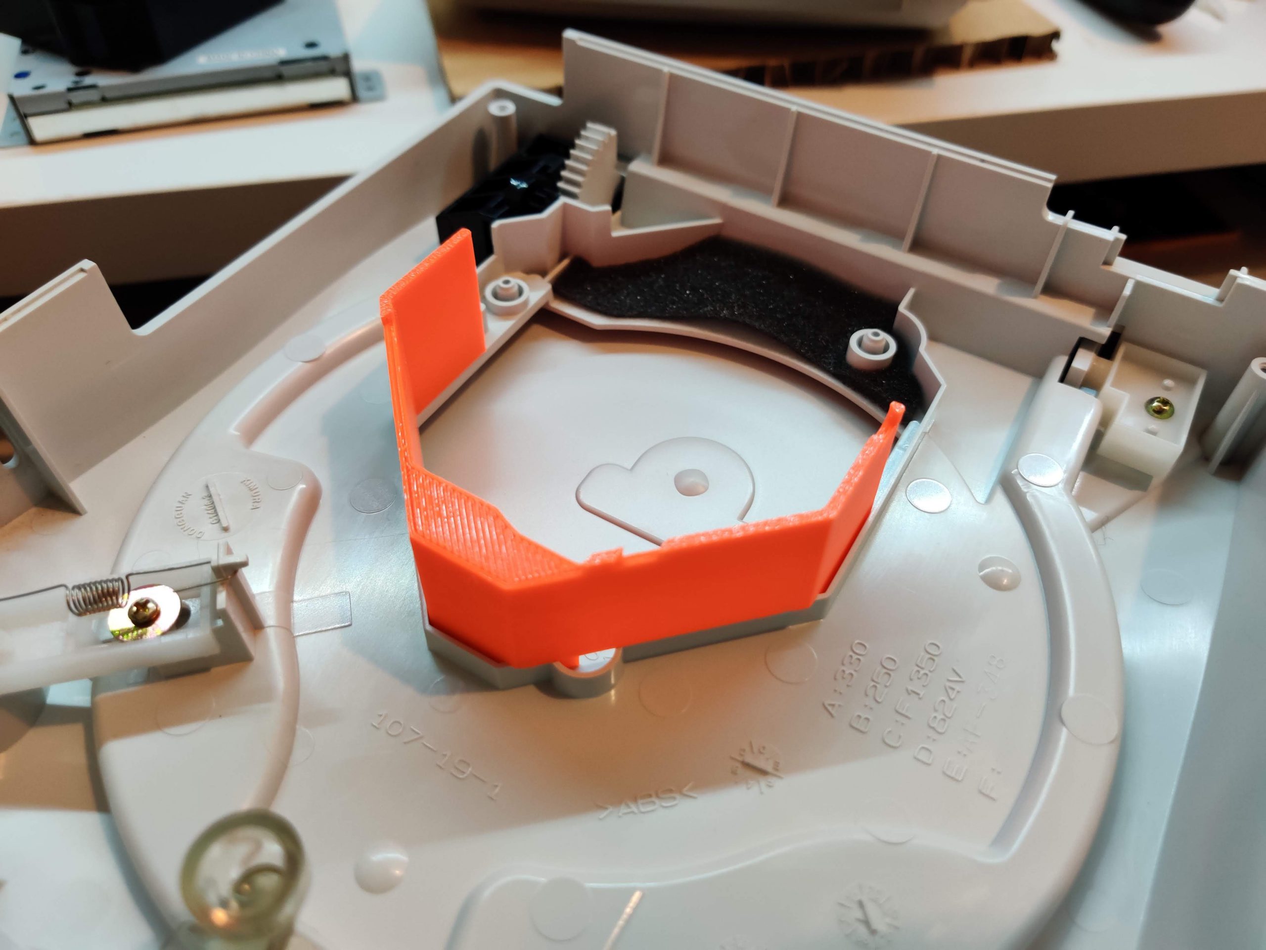
- With the GDEMU in place, now grab the the Dreamcast’s lid as well as the second printed part.
- Line up the 3D printed part to the GD-ROM’s opening in the lid and press fit it. Note: mine was loose so I used a dab of hot glue to hold it in place.
- At this point, you’re finished the GDEMU install and you can close the Dreamcast back up. There is an optional step I highly suggest though if you’ve got a soldering iron.

Removing the 12v Regulator (Optional)
One of the side effects of removing the GD-ROM is increased heat from the 12v rail on the PSU. This is because there is no GD-ROM pulling 12v and lowering the load of that side of the PSU as it was originally designed. An increase of voltage creates a pocket of heat around the 12v regulator. Now, you may not have this issue but my Dreamcast’s case was hot to the touch after only 30 minutes of playing it before I did this mod. That was enough reason for me to remove the 12v regulator.
Things You’ll Need
- Soldering iron or desoldering gun
- Desoldering sucker (if using a soldering iron)
- Philips head screwdriver
Removal Instructions
- Start by unplugging the cable connected to the PSU.
- Now remove the two screws holding the PSU in place.

- Give the PSU a firm upwards tug to remove it from the Dreamcast base.
- With the PSU out of the case, look for the regulator circled below and remove it’s screw.
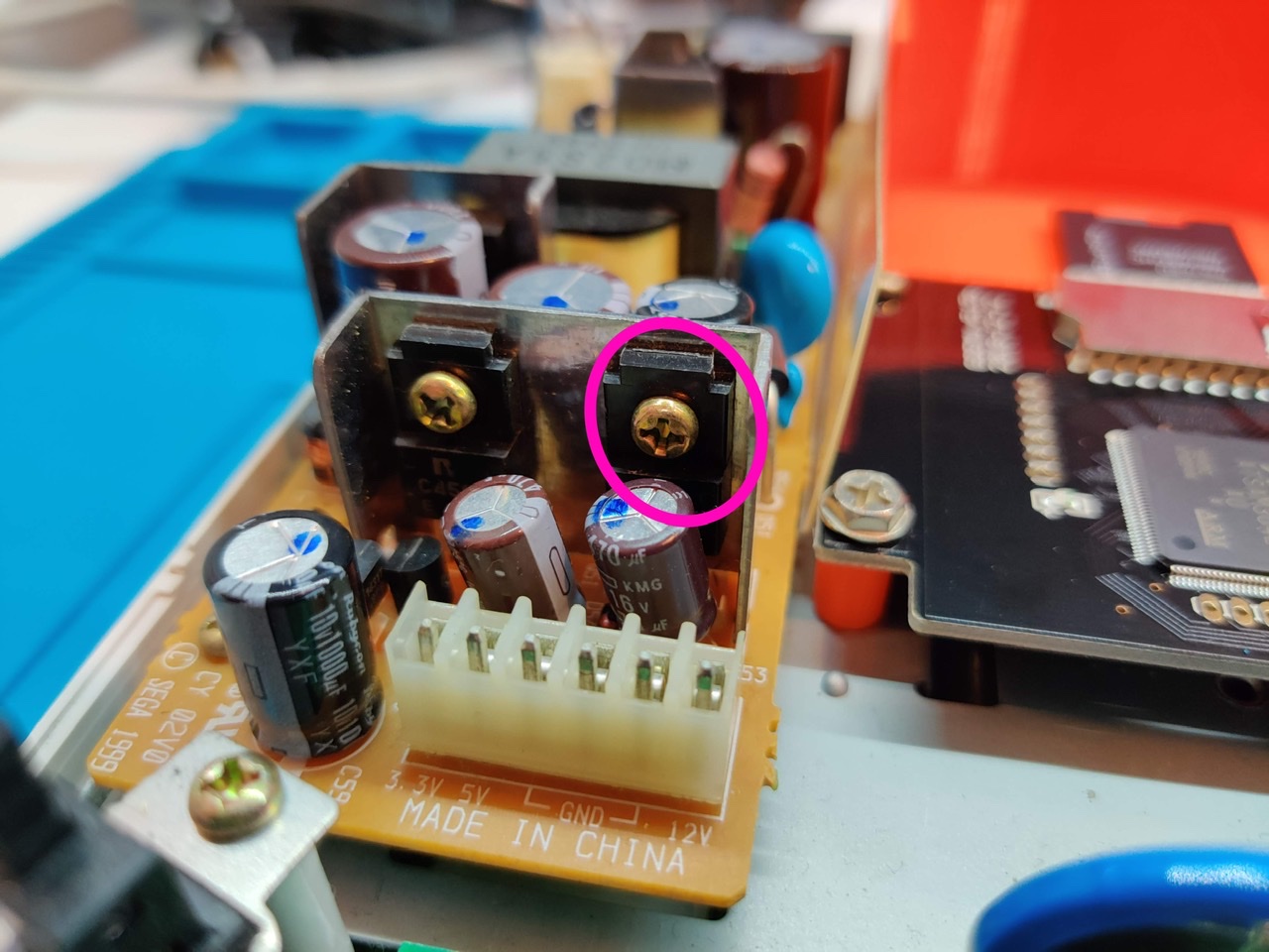
- With the screw removed, flip the PSU over and look for ”R52” and the resistor below it. Immediately beneath the resistor are the three legs from the voltage regulator we’re going to remove.

- Fire up your soldering iron or desoldering station. I’ll be using the Hakko FX-301 because it makes removing through hole parts a breeze. Now desolder the three legs of the regulator.

- That’s it! With the regulator removed from the 12v rail, your Dreamcast will no longer heat up with the GDEMU installed.

Conclusion
As the years and decades pile on, it’s only a matter of time before the optical drives in these consoles break down. For that reason alone, you could make a strong argument for investing in the GDEMU. Another would be the preservation of your working optical drive and it’s media. You could backup your entire library, as I have, and put them safely on display without having to worry about scratchy them or other damage. Sold!