Guides
How to Install Borti’s NESRGB-IGR On A Front Loader NES
One of the cooler features of Tim Worthington’s NESRGB mod is the ability to swap color palettes on the fly. This normally requires installation of a toggle switch of some kind mounted to your NES case. It’s functional but it’s not exactly the most elegant mod. Luckily, there’s a much better solution from an electrical engineer named borti4938 that adds not only palette switching but also console reset all from the NES controller. This install guide is for Borti’s NESRGB-IGR board.
Disclaimer: This post was written for informational purposes only. I assume no liability or responsibility for damaged equipment or for any injury you may incur attempting to replicate this project.
What You’ll Need
This guide assumes you’ve already disassembled the NES and installed Tim’s NESRGB or will do so alongside Borti’s NESRGB-IGR.
- Borti’s NESRGB-IGR board (prebuilt: Voultar’s Mod Shop)
- 4 Pin Headers (comes with Voultar’s board)
- Tim Worthington’s NESRGB
- Soldering Station (I use the KSGER)
- Solder
- 22-24 Gauge Wire
- 28-30 Gauge Wire
- Flush Cutters
- Multimeter (optional for troubleshooting)

Installing the Board
- Start by soldering the pin headers onto the NESRGB where indicated in the photo.
- Place Borti’s NESRGB-IGR board on top of the header and solder the 1, 2, 3, and GND pads to it.
- The goal is to get the board as close to the NESRGB as possible, so nothing is touching the RF shield when the NES is reassembled. Trim the excess pin headers if needed.

Set the Jumper
- Because we’re installing the NESRGB-IGR on a front loader NES, set the small jumper to “HI” by soldering the two pads circled in blue.
- If this step is missed, the NES won’t boot.

3.3v Power Line
- Using the 22-24 gauge wire, measure from the 3.3v pad of the NESRGB-IGR board to the surface mounted Capacitor shown in the picture, then cut the wire to length using your flush cutters.
- Strip and tin both sides of the wire you just cut to length. I’m not going to mention stripping and tinning wires past this point, since it should be a common practice.
- Solder one side to the 3.3v pad and the other to the surface mounted capacitor.
- Make sure you’re soldering to the correct side of the capacitor. If you’re unsure, use a multimeter to find the ground side but solder to the positive side of the cap.
- Alternative 3.3v solder location

5v Power Line
- Using the 22-24 gauge wire and the technique of measuring to length, measure wire from the NESRGB-IGR pad to the pictured capacitor.
- Solder one side of the wire to the 5v pad on the NESRGB-IGR and the other on the pictured surface mounted capacitor.
- Make sure you’re soldering to the correct side of the capacitor. If you’re unsure, use a multimeter to find the ground side, you want the positive side of the cap.
- Alternative 5v solder location
Controller Port Wiring
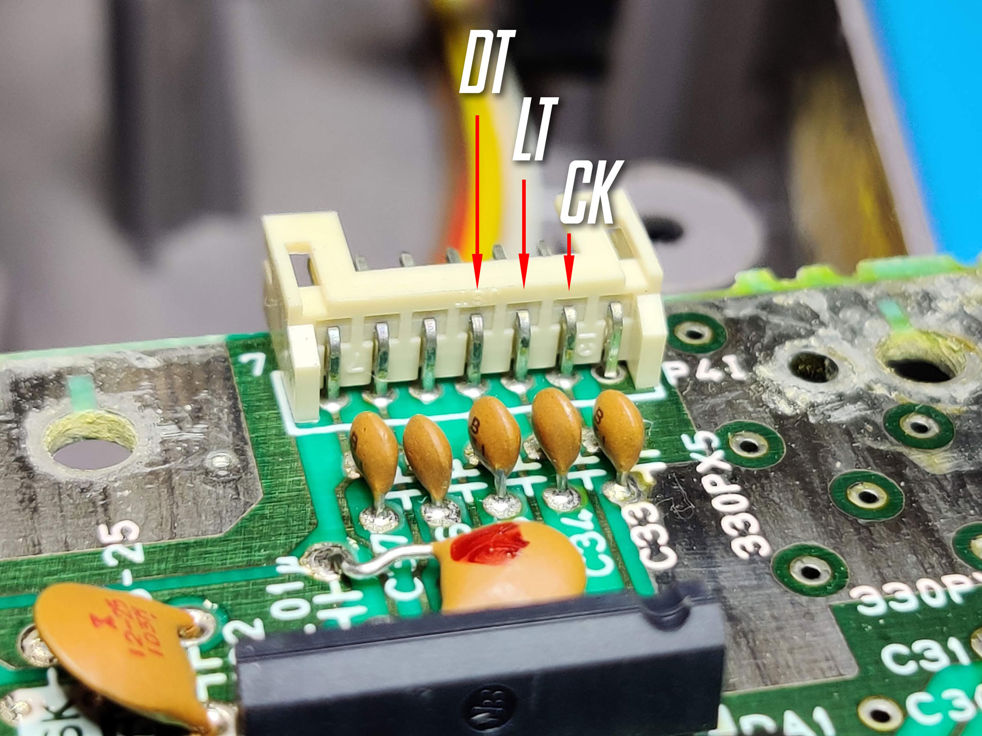
- Find the player 1 controller port JST connector on the NES’ motherboard. This should be the connector facing the front of the NES.
- Apply some solder on the “DT”, “LT”, and “CK” pins on the connector indicated in the photo (pin 2, 3 and 4 from right to left).
- Take the 28-30 gauge wire and use the measuring technique for the appropriate length.
- Solder the DT, LT, and CK wires on the JST connector.
- Solder the other end of signal wires to Borti’s NESRGB-IGR board. The pads are marked accordingly.

Reset Button Wiring
- Locate the blue 5 pin Reset/Power button board connector on the NES motherboard.
- Using the flush cutters, cut a small chunk out of pin 4. Be careful not to cut too close to the blue connector.
- The idea here is you’re breaking the connection between the pin and the motherboard so the NESRGB-IGR can intercept the signal. From this point forward, I will refer to the top of pin 4 as “RI” and the bottom part of pin 4 as “RO”.
- Using the 28-30 gauge wire, measure 2 wires from the blue connect to the NESRGB-IGR board’s “RO” and “RI” pads.
- Now wire up the pin 4’s RI (top) and RO (bottom) to the appropriate RI/RO pads on the NESRGB-IGR.

Double Check The Install
It’s always a good idea to check your install before powering on the NES.
Check the following:
- The NESRGB-IGR board is level and parallel to the NESRGB.
- Make sure the NESRGB-IGR does not make contact with the bottom RF shield.
- Proper Jumper is set (“HI” for front loader NES)
- Voltage lines are wired to the correct locations
- CK, LT, and DT are correctly wired
- Pin 4 RI and RO are wired correctly
Test Your Install
With everything checked out reassemble the NES part way, since it’s a good idea to test everything before completely reassembling the NES just in case something doesn’t work as expected. That being said, reattach the 72-pin cartridge connector to the motherboard, slide the cart tray around the connector, reconnect the controller ports, reconnect the blue power/reset connector, reattach your RGB AV connection, and finally put the motherboard back in the bottom case. Make sure to insert a game cartridge, power, and controller for testing then power on your NES.
Controller:
- Short Reset: START + SELECT + A + B for less than 2 sec.
- Flash Cart Menu: START + SELECT + A + B for longer than 2 sec.
- Palette Forward: START + SELECT + D-PAD >
- Palette Backward: START + SELECT + D-PAD <
NES Reset Button:
- Short Reset: Short push for less than a sec.
- Long Reset: Second push and hold to fully reset PIC.
- Palette Switch: Press and hold to cycle through palettes.
Troubleshooting
The NES powers on but the palettes keep switching
You most likely have your “RO” and “RI” wires mixed up.
The NES no longer powers on
– Check to make sure the Jumper is set properly.
– Check pin 4 is wired correctly and separated from one another.
In game reset doesn’t work
This can also be a mismatch of “RI” and “RO” wires but you’d see see the palette cycling too. Check the controller “CK, “LT”, “DT” wiring and ensure they’re going to the correct NESRGB-IGR board pads.